
To deploy a network for a new branch, a WiFi network "SSID-FREE" is provided for external personnel for free. The WLAN for clients on floor 3 is divided into VLAN 10, and the WLAN for clients on floor 4 is divided into VLAN 20. The roaming function is supported, and the uplink and downlink rates of all clients are limited to 100 Kbps.
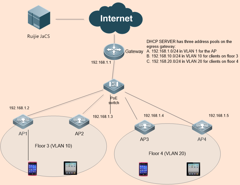
Network planning is realized using Network.
Step 1: Choose CONFIGURATION > NETWORKS.
Step 2: Click Add Network to add “TestHotel” Network.
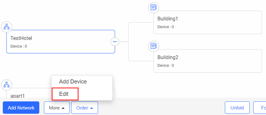
Step 3: Click Add Sub Network to add “Building1” and “Building2” network, as shown in the following figure. You can add more networks according to this method.

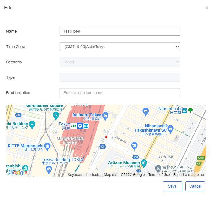
Step 4: Choose CONFIGURATION > NETWORKS > More > Edit, and select the TestHotel network.
Step 5: Enter a location name in the search box, select the location marked by  on the map, and then click Save.
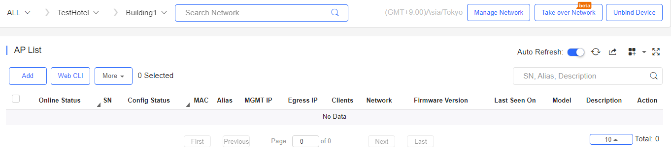
Step 6: Choose MONITORING > DEVICE > AP, select the TestHotel > Building1 network, and click Add to add APs. APs can be imported in batches or added one by one. Accordingly, add other APs in the TestHotel > Building2 network.
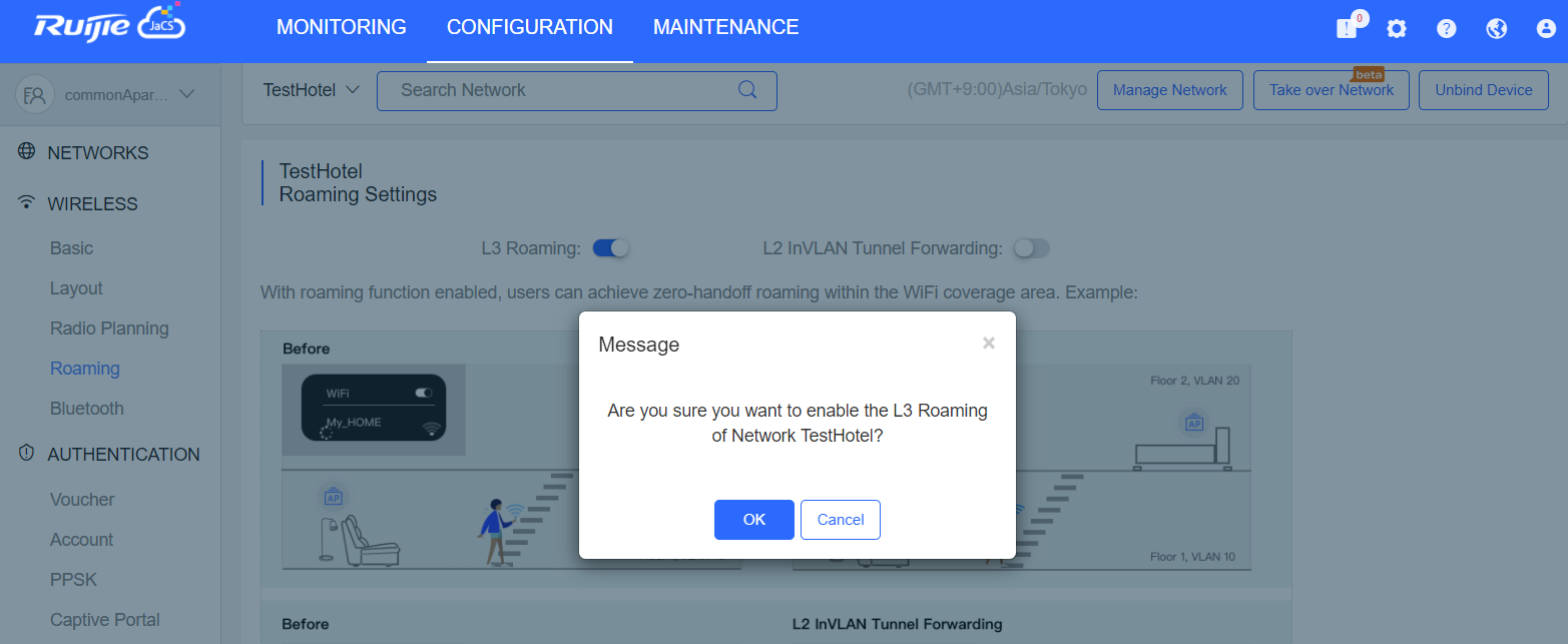
Step 1: Choose CONFIGURATION > WIRELESS > Roaming.
Step 2: Select the TestHotel network (non-apartment network).
Step 3: Enable the roaming function for this Network.
Step 1: Choose CONFIGURATION > WIRELESS > Basic.
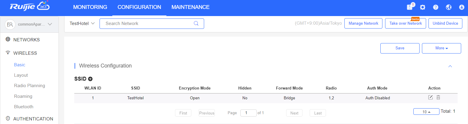
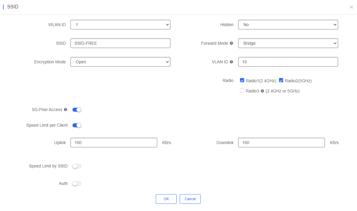
Step 2: Click + under SSID, enter SSID-FREE in the SSID text box, set Forward Mode as Bridge, set VLAN ID as 10, set Rate limit as 100 KB/s, and click Save.
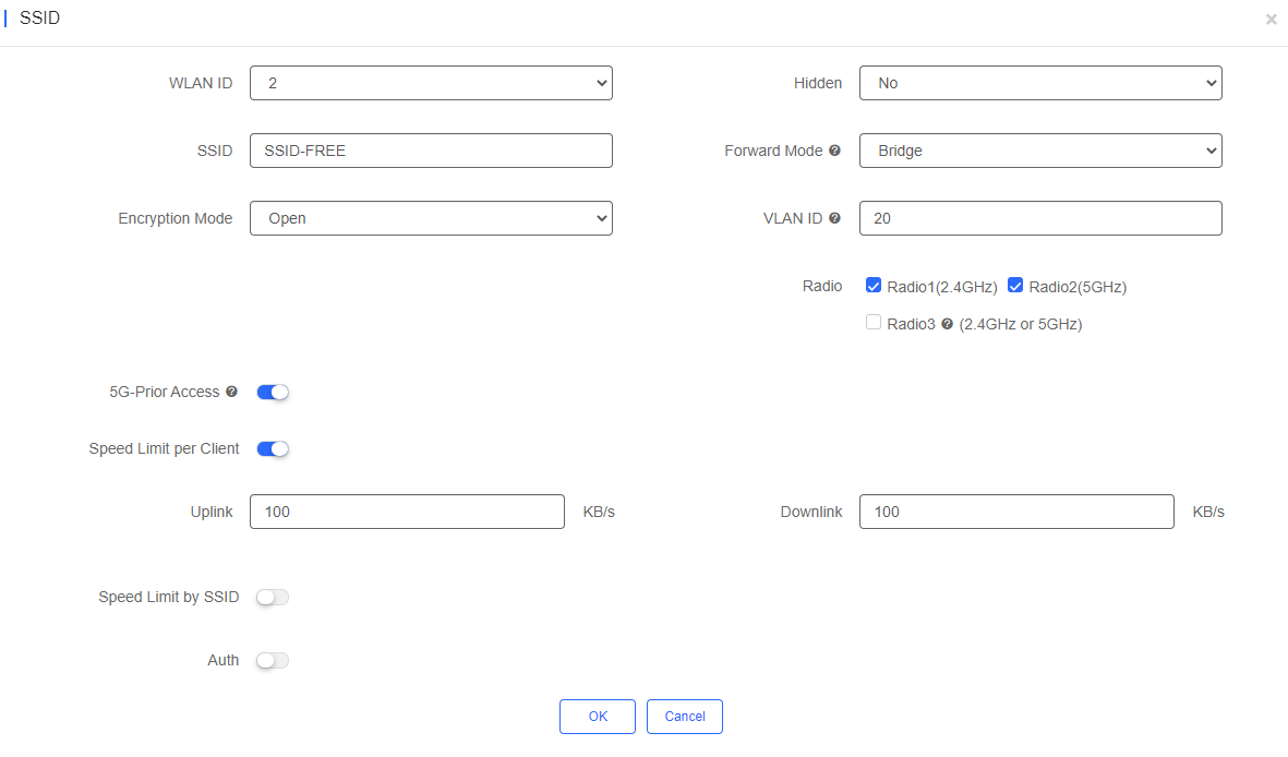
Step 3: Add the Building2 network with VLAN ID 20 according to the same method.
Bind AP1 and AP2 to the Building1 network, and bind AP3 and AP4 to the Building2 network.
Add the AP address pool: 192.168.1.0/24.
Building1 client address pool: 192.168.10.0/24; gateway: 192.168.10.1; VLAN: 10
Building2 client address pool: 192.168.20.0/24; gateway: 192.168.20.1; VLAN: 20
On the port through which the PoE switch is connected to the AP, configure a trunk port with the native ID set to 1 by default, and add VLAN 10 and VLAN 20.
Connect a mobile phone to the WiFi network properly for Internet access.
Connect a mobile phone with the WiFi network “SSID-FREE”, and go upstairs from Building1 to Building2. Reconnection and Internet access failure do not occur.
全部评论